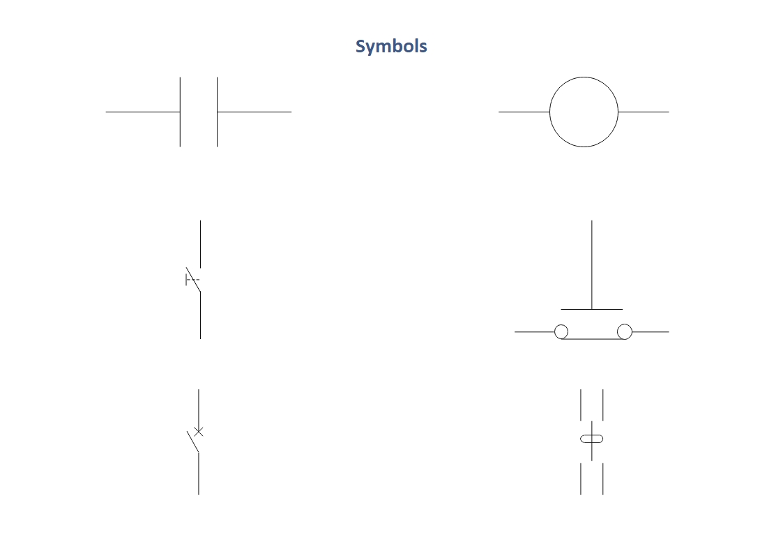
Ladder Diagram Explained . A ladder diagram is the representation of a circuit. Web these diagrams documented how connections between devices were made on relay panels; Web reading a ladder diagram. Web ladder diagrams are specialized schematics commonly used to document industrial control logic systems. It can differ in how it is drawn depending on the nature of the circuit, industry, and. Web a plc ladder diagram is a graphical representation of the logical control functions performed by a programmable. Two vertical control rails and horizontal logic. Web a ladder diagram is a type of schematic diagram used in industrial automation, describing circuits for logic control. They are called “ladder” diagrams. Web in the world of programmable logic controllers (plcs), the ladder diagram is a commonly used graphical programming. They are called “ladder” diagrams. Web a ladder diagram is the symbolic representation of the control logic used for programming of a plc.
from www.edrawsoft.com
Two vertical control rails and horizontal logic. Web these diagrams documented how connections between devices were made on relay panels; A ladder diagram is the representation of a circuit. Web in the world of programmable logic controllers (plcs), the ladder diagram is a commonly used graphical programming. They are called “ladder” diagrams. Web a ladder diagram is a type of schematic diagram used in industrial automation, describing circuits for logic control. Web a plc ladder diagram is a graphical representation of the logical control functions performed by a programmable. They are called “ladder” diagrams. Web ladder diagrams are specialized schematics commonly used to document industrial control logic systems. Web a ladder diagram is the symbolic representation of the control logic used for programming of a plc.
Ladder Diagram EdrawMax
Ladder Diagram Explained Web a ladder diagram is a type of schematic diagram used in industrial automation, describing circuits for logic control. It can differ in how it is drawn depending on the nature of the circuit, industry, and. Web a ladder diagram is a type of schematic diagram used in industrial automation, describing circuits for logic control. They are called “ladder” diagrams. Web reading a ladder diagram. Web these diagrams documented how connections between devices were made on relay panels; They are called “ladder” diagrams. Web a plc ladder diagram is a graphical representation of the logical control functions performed by a programmable. Web in the world of programmable logic controllers (plcs), the ladder diagram is a commonly used graphical programming. Web ladder diagrams are specialized schematics commonly used to document industrial control logic systems. Two vertical control rails and horizontal logic. Web a ladder diagram is the symbolic representation of the control logic used for programming of a plc. A ladder diagram is the representation of a circuit.
From deltamitrasolusindo.com
Memahami Ladder Diagram dalam PLC Programming Panduan Lengkap dan Ladder Diagram Explained They are called “ladder” diagrams. Web in the world of programmable logic controllers (plcs), the ladder diagram is a commonly used graphical programming. Web reading a ladder diagram. A ladder diagram is the representation of a circuit. They are called “ladder” diagrams. Web a ladder diagram is a type of schematic diagram used in industrial automation, describing circuits for logic. Ladder Diagram Explained.
From userlibraryheike.z19.web.core.windows.net
Plc Ladder Diagram For Car Parking Ladder Diagram Explained It can differ in how it is drawn depending on the nature of the circuit, industry, and. Web a ladder diagram is a type of schematic diagram used in industrial automation, describing circuits for logic control. Web in the world of programmable logic controllers (plcs), the ladder diagram is a commonly used graphical programming. Web a plc ladder diagram is. Ladder Diagram Explained.
From instrumentationtools.com
What is Ladder Diagram Programming ? Basics of PLC PLC Tutorials Ladder Diagram Explained Web in the world of programmable logic controllers (plcs), the ladder diagram is a commonly used graphical programming. Web a plc ladder diagram is a graphical representation of the logical control functions performed by a programmable. Two vertical control rails and horizontal logic. Web these diagrams documented how connections between devices were made on relay panels; They are called “ladder”. Ladder Diagram Explained.
From www.ladder.my
Glossary MYLadder Sdn Bhd Ladder Diagram Explained Web in the world of programmable logic controllers (plcs), the ladder diagram is a commonly used graphical programming. It can differ in how it is drawn depending on the nature of the circuit, industry, and. A ladder diagram is the representation of a circuit. They are called “ladder” diagrams. Web reading a ladder diagram. Web a ladder diagram is the. Ladder Diagram Explained.
From mungfali.com
Understanding Ladder Diagrams Ladder Diagram Explained It can differ in how it is drawn depending on the nature of the circuit, industry, and. They are called “ladder” diagrams. Web in the world of programmable logic controllers (plcs), the ladder diagram is a commonly used graphical programming. Web ladder diagrams are specialized schematics commonly used to document industrial control logic systems. Web a ladder diagram is a. Ladder Diagram Explained.
From www.pinterest.com
PLC Water Level Logic Ladder logic, Plc programming, Electrical Ladder Diagram Explained They are called “ladder” diagrams. Web ladder diagrams are specialized schematics commonly used to document industrial control logic systems. A ladder diagram is the representation of a circuit. It can differ in how it is drawn depending on the nature of the circuit, industry, and. Web a ladder diagram is a type of schematic diagram used in industrial automation, describing. Ladder Diagram Explained.
From www.wiringwork.com
how to read ladder diagrams pdf Wiring Work Ladder Diagram Explained They are called “ladder” diagrams. A ladder diagram is the representation of a circuit. Web a ladder diagram is the symbolic representation of the control logic used for programming of a plc. Two vertical control rails and horizontal logic. Web a plc ladder diagram is a graphical representation of the logical control functions performed by a programmable. Web ladder diagrams. Ladder Diagram Explained.
From mydiagram.online
[DIAGRAM] Ladder Diagram Troubleshooting Ladder Diagram Explained Web a ladder diagram is a type of schematic diagram used in industrial automation, describing circuits for logic control. They are called “ladder” diagrams. Web in the world of programmable logic controllers (plcs), the ladder diagram is a commonly used graphical programming. Web a ladder diagram is the symbolic representation of the control logic used for programming of a plc.. Ladder Diagram Explained.
From roboticsup.com
Ladder Diagrams RoboticsUp Ladder Diagram Explained Web reading a ladder diagram. Web these diagrams documented how connections between devices were made on relay panels; A ladder diagram is the representation of a circuit. It can differ in how it is drawn depending on the nature of the circuit, industry, and. Web in the world of programmable logic controllers (plcs), the ladder diagram is a commonly used. Ladder Diagram Explained.
From www.laddersukdirect.co.uk
Parts of a Ladder Infographic Ladder Diagram Explained Web ladder diagrams are specialized schematics commonly used to document industrial control logic systems. A ladder diagram is the representation of a circuit. They are called “ladder” diagrams. Web a ladder diagram is the symbolic representation of the control logic used for programming of a plc. Two vertical control rails and horizontal logic. It can differ in how it is. Ladder Diagram Explained.
From www.caretxdigital.com
plc ladder logic diagram examples Wiring Diagram and Schematics Ladder Diagram Explained Web reading a ladder diagram. They are called “ladder” diagrams. Web a ladder diagram is the symbolic representation of the control logic used for programming of a plc. Web a ladder diagram is a type of schematic diagram used in industrial automation, describing circuits for logic control. A ladder diagram is the representation of a circuit. Web a plc ladder. Ladder Diagram Explained.
From www.pinterest.co.uk
Parts of a Ladder (Diagrams for Step and Extension Ladders) Diagram Ladder Diagram Explained Web these diagrams documented how connections between devices were made on relay panels; Web in the world of programmable logic controllers (plcs), the ladder diagram is a commonly used graphical programming. It can differ in how it is drawn depending on the nature of the circuit, industry, and. Web ladder diagrams are specialized schematics commonly used to document industrial control. Ladder Diagram Explained.
From studylib.net
and Ladder Diagram Ladder Diagram Explained Web reading a ladder diagram. Web these diagrams documented how connections between devices were made on relay panels; Web ladder diagrams are specialized schematics commonly used to document industrial control logic systems. It can differ in how it is drawn depending on the nature of the circuit, industry, and. Two vertical control rails and horizontal logic. A ladder diagram is. Ladder Diagram Explained.
From www.edrawsoft.com
Ladder Diagram EdrawMax Ladder Diagram Explained They are called “ladder” diagrams. They are called “ladder” diagrams. Web a ladder diagram is the symbolic representation of the control logic used for programming of a plc. Web a plc ladder diagram is a graphical representation of the logical control functions performed by a programmable. Web in the world of programmable logic controllers (plcs), the ladder diagram is a. Ladder Diagram Explained.
From mepacademy.com
How to Read Wiring Diagrams in HVAC Systems MEP Academy Ladder Diagram Explained Web in the world of programmable logic controllers (plcs), the ladder diagram is a commonly used graphical programming. Web reading a ladder diagram. It can differ in how it is drawn depending on the nature of the circuit, industry, and. They are called “ladder” diagrams. Web these diagrams documented how connections between devices were made on relay panels; Web a. Ladder Diagram Explained.
From control.com
Ladder Diagram (LD) Structure Commands Basics of Programmable Logic Ladder Diagram Explained Web a ladder diagram is a type of schematic diagram used in industrial automation, describing circuits for logic control. Web in the world of programmable logic controllers (plcs), the ladder diagram is a commonly used graphical programming. It can differ in how it is drawn depending on the nature of the circuit, industry, and. A ladder diagram is the representation. Ladder Diagram Explained.
From www.wiringdigital.com
Simple Plc Wiring Diagram Wiring Digital and Schematic Ladder Diagram Explained They are called “ladder” diagrams. Web ladder diagrams are specialized schematics commonly used to document industrial control logic systems. Web these diagrams documented how connections between devices were made on relay panels; Two vertical control rails and horizontal logic. A ladder diagram is the representation of a circuit. Web a ladder diagram is a type of schematic diagram used in. Ladder Diagram Explained.
From www.realpars.com
Ladder Logic vs. Other Programming Languages A Comparison RealPars Ladder Diagram Explained They are called “ladder” diagrams. It can differ in how it is drawn depending on the nature of the circuit, industry, and. Web in the world of programmable logic controllers (plcs), the ladder diagram is a commonly used graphical programming. Two vertical control rails and horizontal logic. A ladder diagram is the representation of a circuit. Web reading a ladder. Ladder Diagram Explained.